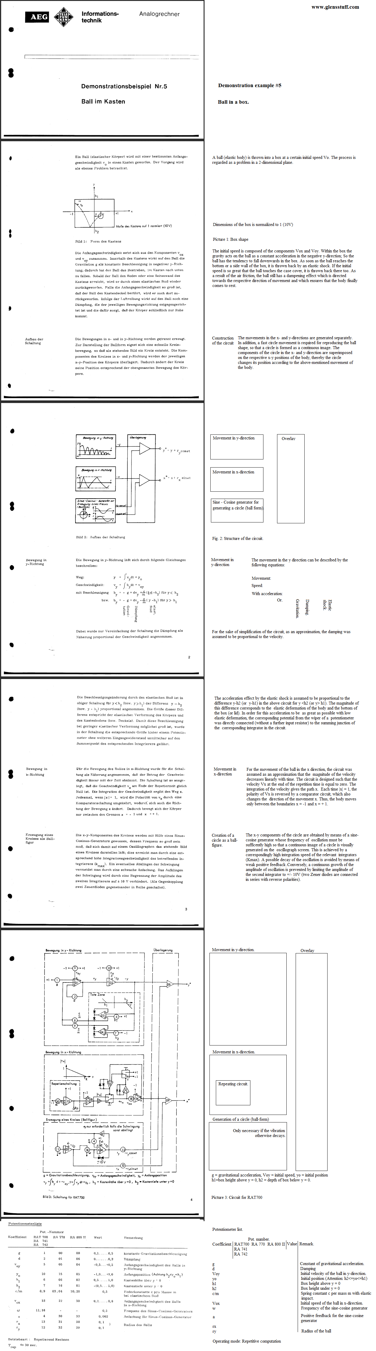
Detailed on this page is my implementation of the simulation on solder-less breadboard, demonstrating the utility of my newly completed (at the time of writing) large-screen, electromagnetic- deflection X-Y oscilloscope, designed and built as a component for my, as yet incomplete, GK-1 analog computer system. I also translated the originally German paper to English.
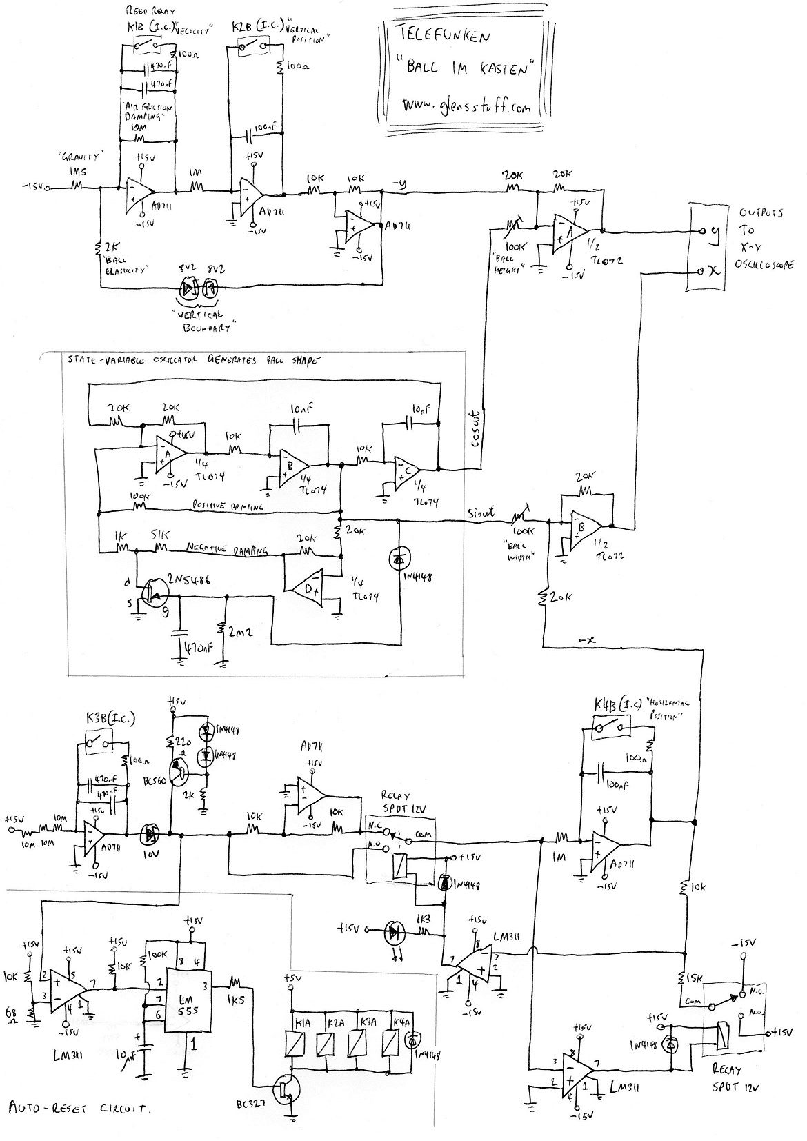
The hand-drawn schematic diagram attached below shows the complete functional circuit as assembled on the breadboard as seen in the demonstration video above; only the necessary integrated circuit supply-rail bypass capacitors being omitted, for clarity.
For the sine-cosine generator which generates the ball form I assembled a generic state-variable oscillator fundamentally similar in principle to that described in the paper by Telefunken, though my integrated op-amp implementation uses a simple JFET-based automatic gain control circuit to stabilise the amplitude of oscillation. Imagine that power has just been applied and oscillations of significant amplitude have not yet started. Positive damping feedback is provided via the 100k resistor while negative damping feedback via the parallel path is temporarily muted by the fully-turned-on JFET (the gate-source potential of the JFET is currently 0V). As a consequence of the positive damping, oscillation begins and the amplitude of oscillations grow. The FETs negative DC gate potential is produced by half-wave rectifying and filtering the oscillators output signal. As oscillations grow in amplitude the JFET is progressively forced towards the off state until (approximately) equilibrium is eventually reached; the parallel negative damping feedback at that point cancelling the positive. The frequency of oscillation is approximately 1600 Hz, governed by both the gain (-1 Av) of the loop inverting stage and the R and C component values of the respective integrators.
The circuits total simulation time for the problem is approximately 20 seconds and it endlessly resets and repeats itself (so long as power remains applied!) courtesy of an automatic reset-circuit which senses the end of the solution; then reinstating initial conditions. The end of the solution is detected by the LM311 comparator monitoring the output of the velocity integrator of the x-movement circuit. Once this potential has linearly ramped down to 0V from 10V (at which point horizontal movement of the ball has become stationary) the LM311 triggers the 555-timer-based monostable which activates relays K1 through K4 for approximately two seconds. This reinstates initial conditions as the contacts of relays K1 through K4 short-out and thus discharge, to zero volts, the potential across the capacitors of the simulations four position and movement-computing integrators.
I assembled this simulation out of components which I readily had at hand. At the time I thought that solid-state analogue switches would have been a more elegant solution to the numerous relays used. That may be true electrically, but there is, admittedly, something delightful in hearing the x-movement circuit's direction-control relays simultaneously click either on or off every time the ball hits one of the walls of the box! It is these relays which are producing the clicking noise audible in the posted video.