This little 'scope, for what it is, is reasonably sophisticated, actually having a proper frequency-compensated attenuator for the vertical amplifier channel with specified sensitivities. The specified bandwidth is 4 MHz on the lowest vertical sensitivity.
The horizontal deflection amplifier design is a bit unusual. A triode cathodyne phase-splitter provides the complementary sweep waveforms to drive the horizontal deflection plates. The signals from the cathodyne are capacitively coupled to the plates and the plates are DC biased so that (in the absence of a sweep waveform from the timebase circuit) the beam is deflected off screen to the left. To center the sweep the saw-tooth sweep waveforms at the deflection plates are DC-restored by (hollow state*) diode clamps. There arent any horizontal position or horizontal size and gain controls, so you won't see/get anything on the C.R.T. if the timebase is dead and not oscillating, and quite dead my timebase was.
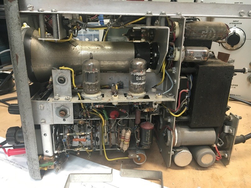
Starting at the trigger input circuit for the timebase I found the first dud component noticing that some tube biasing potentials didn't measure right. A 680k resistor measured open circuit. With this resistor replaced the respective pentode stage still didn't appear to bias properly and this was further found to be due to a dud low emission pentode (half of a 9A8 triode-pentode dual). After some searching through my NOS Miniwatt tube stash I found a 6BL8, which is a direct 9A8 equivalent. Substituting the dud tube caused the timebase to spring to life, but the saw-tooth horizontal sweep waveforms still weren't appearing at the horizontal deflection plates and I still didn't have anything visible on the C.R.T..
Probing the cathodyne stage immediately identified it as being dud. It wasn't biased properly, the cathode DC potential with no signal input being only a few volts above ground rather than a couple of hundred or so. The issue was traced to the 15k plate load resistor which measured open circuit. After replacing the dud 15k resistor the cathodyne sprung to life and I had proper complementary saw-tooth sweep waveforms at the cathode and plate.
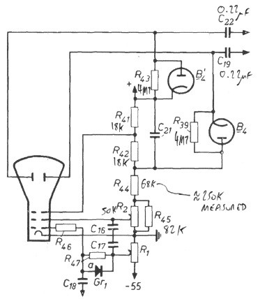
That was the timebase and horizontal amplifier sorted, but the resulting signal trace on the C.R.T. was still mostly deflected off screen to one side and all wonky and out of focus. I computed the DC potentials throughout the C.R.T. circuit from the schematic diagram and compared these to measurements with my D.V.M.. The voltages were well out and the cause traced to a 68k resistor that measured over 250k. It is, unfortunately, quite common for these old resistors to deteriorate with age and go dramatically high in value.
With the dud 68k resistor replaced the C.R.T. circuit biasing voltages came up as predicted and the portion of trace visible could then be adequately focused, but the horizontal deflection was still not right as most of the signal trace remained deflected off one side of the screen. The DC potential at one of the horizontal deflection plates (measured with a 100M-ohm 100:1 probe for minimal loading and reasonable accuracy, as the DC resistance to ground here is fairly high at approximately ~4.7M-ohm) was a couple of hundred volts too low. I took a punt that the 220nF signal coupling capacitor to this deflection plate was leaky, thus pulling the plates DC potential down towards the cathodyne's plate potential. This was verified by disconnecting one end of the capacitor and then witnessing the deflection plate DC potential return to the ~ +430V that it was supposed to be at. Some scrounging through my junk capacitor box eventually produced a 220nF 630V polyester capacitor, which was promptly soldered in to substitute the dud.
Bingo! Five dud components down and I then had a seemingly fully functionally GM5650, but still far from fully restored though. Many of the resistors still measure somewhat high and a lot of the ancient big black capacitors look so badly deteriorated from the outside that it's a wonder that they haven't all gone leaky to an unworkable degree either.
I also had to repair the C.R.T. itself. The C.R.T. is a Philips-made DG7-32, of which I have several Mullard-made spares. As is not atypical for these old tubes the glue bonding the pin
base to the glass envelope had given out. I carefully and gently extracted the C.R.T. from the scope (so as to not bust the interconnecting wires inside the pin base) and then re-bonded the base
to the glass with some 24-hr Araldite. It was shortly after doing this repair that I learnt that none of my Mullard DG7-32's could be used as a substitute for that Philips one. To avoid waiting for the
Araldite to harden I tried to plug in one of my Mullard C.R.T.s, but it became a snug fit inside the mu-metal shield well before the base pins could properly mate with the socket. Compared to
the Mullard DG7-32's, the neck of the Philips-made equivalent is ~12mm longer!
* "hollow state", as opposed to solid state.
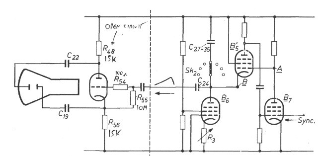
The cathodyne phase splitter.
The horizontal deflection plate signal DC restoration circuit.
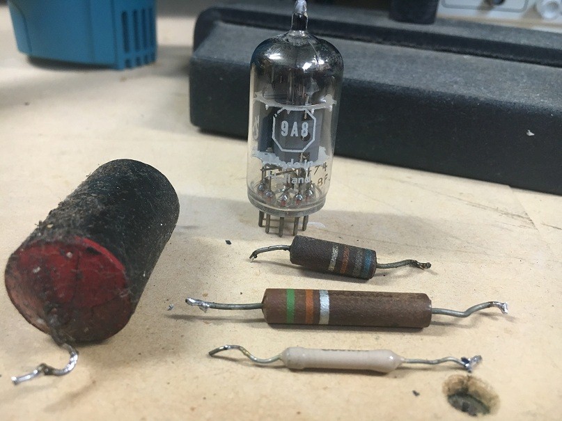
The three high-value resistors, the leaky coupling cap and the dud tube.
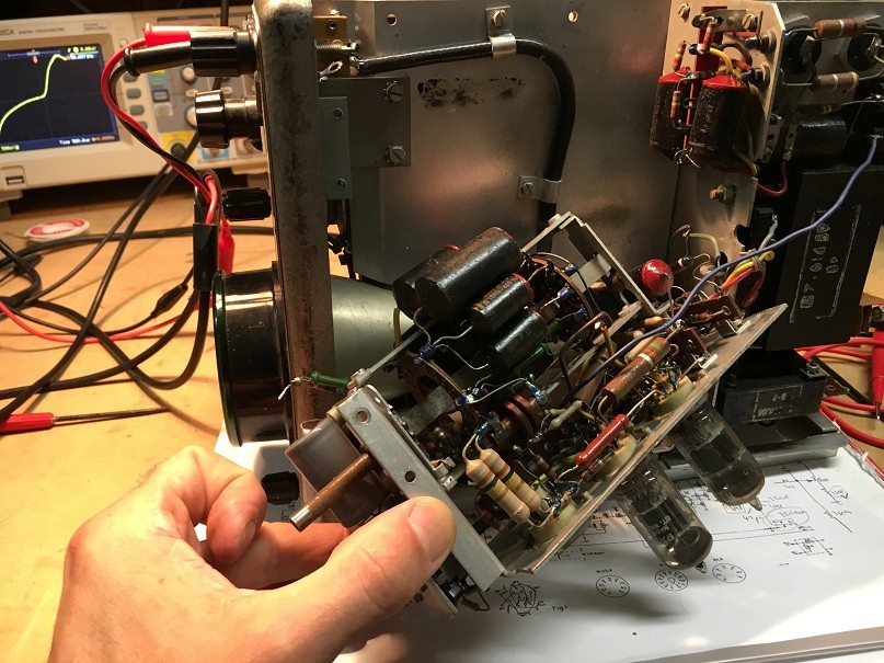
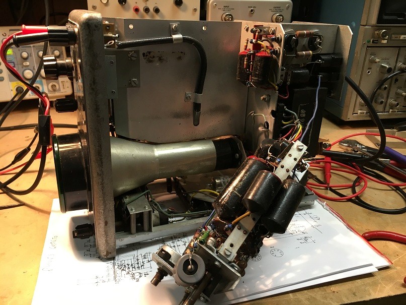
The timebase chassis removed for component access.
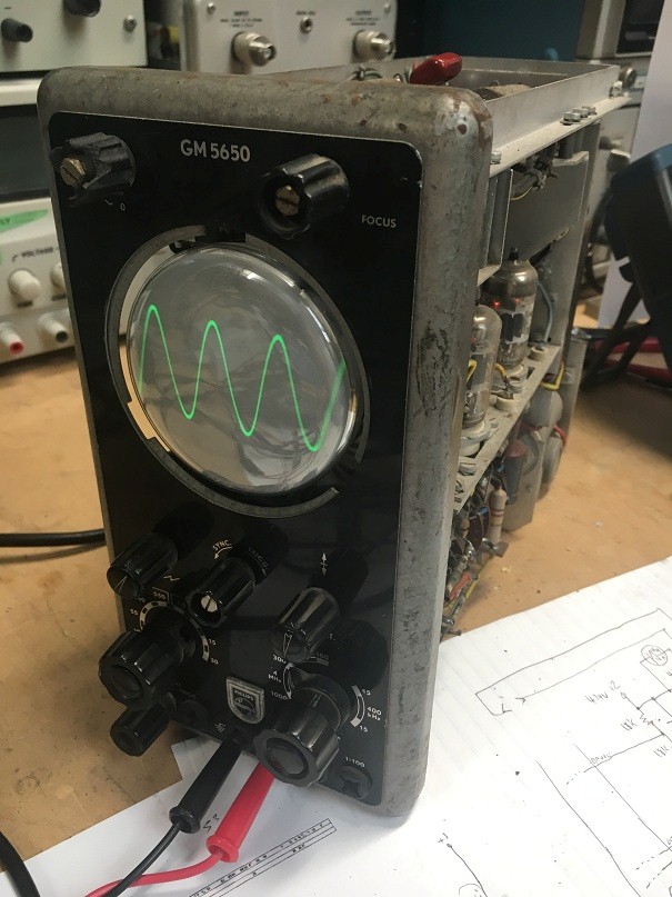
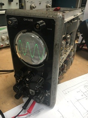
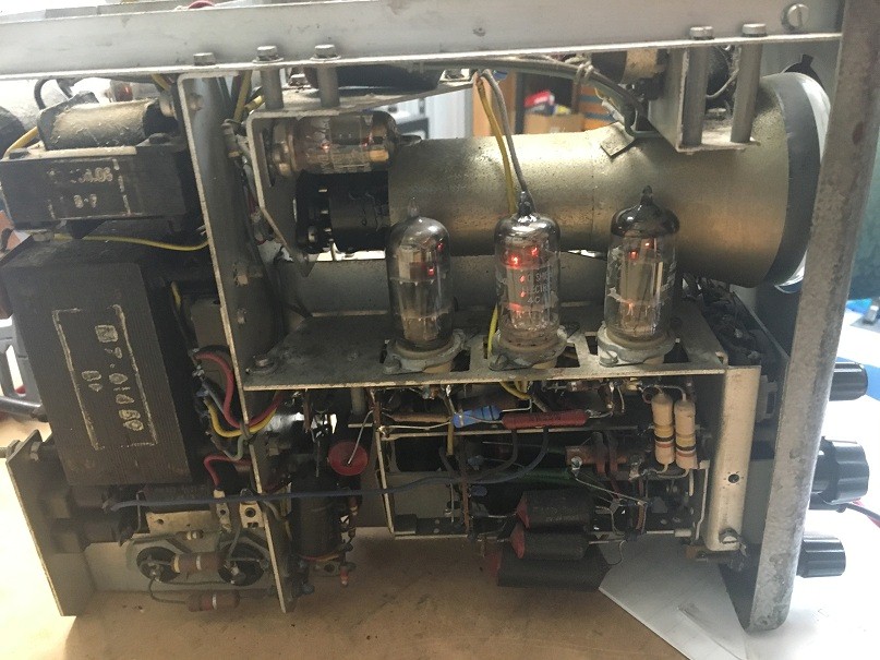
It's alive!.